1982 Yamaha XJ750 Seca
Side Cover Post & "C" Mount Repair


This is one possible method for repairing a broken off mounting post on the side cover of a 1982 XJ750 Seca. The post had broken off once before and was then welded on by a professional but promptly broke off again. I offered to have a look at the situation and decided to abandon the broken off post in favour of creating a new one which I hope will be stronger and more durable. With time spent taking pictures to document the repair, the whole process took less than three hours but it could easily have been done in less than one without the documentation. Time will tell how it holds up.

1
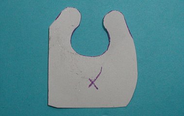
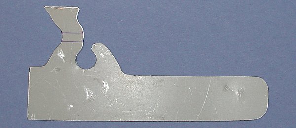
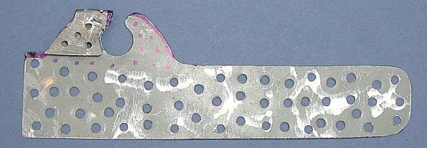
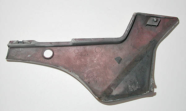
To repair the broken off and missing side cover mounting post it's helpful to have a spare side cover as a template. If you don't have a spare, then borrowing a side cover will also work. The borrowed cover won't be harmed in the process and would only be necessary very briefly.
2
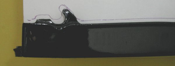
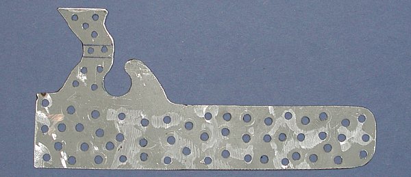
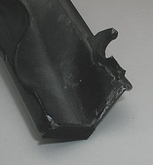
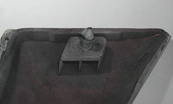
The spare or borrowed cover must have a good mounting post. It will be used to make a mould to create a new post.
3
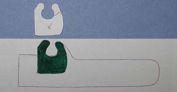
There are bound to be many creative ways to make a mould but I found it easiest to use a floral Oasis block. Oasis blocks are cheap (less than $1), easy to cut and don't rebound after being deformed around an object. I used a small piece of an Oasis block and cut it in half.
4
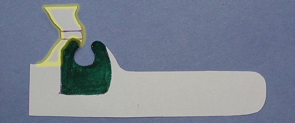
Simply press the two halves of Oasis block onto the good post from opposite sides, then fasten the two halves together using an elastic band.
5
Since the post may not be symmetrical and the impression in the Oasis block may be less than perfect, the mould can be improved by spinning it around.
6
Spin the Oasis block around while keeping pressure on both halves to make sure you end up with a clean symmetrical impression.
7
Remove the elastic band from the Oasis block and separate the two halves. If all went well, you should have a reasonably good impression for a mould.
8
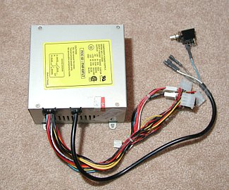
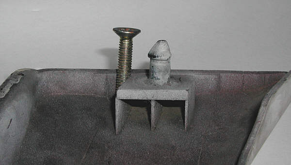
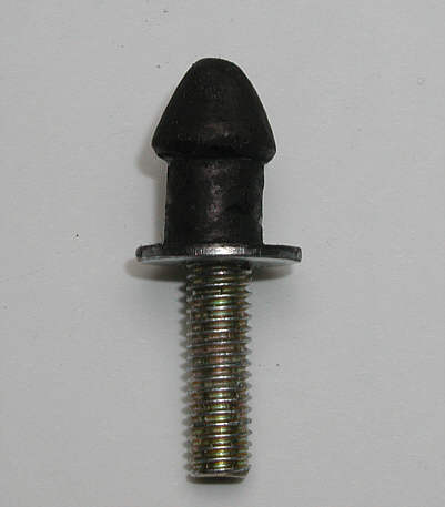
The new post will have to be formed around a more solid core if you don't want it to break again. For strength, anchorage and adhesion reasons, a threaded steel rod is good but a screw may be better because the head can be used to help form the knob at the end of the new mounting post. Find a screw with a thread diameter that's slightly narrower than the shaft of the original mounting post. Make sure the screw is long enough that it can be threaded right to the bottom of the mounting post base (ie. the inside surface of the side cover). I used the pictured screw but made some modifications to it later.
9
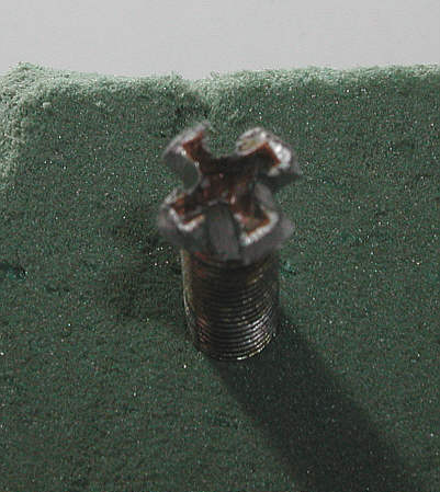
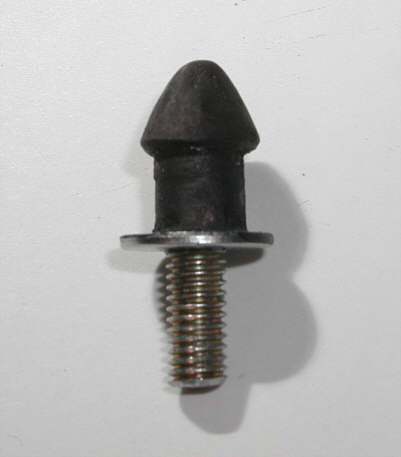
It was necessary to grind down the diameter of the head of the screw to something less than the maximum diameter of the knob at the end of the mounting post. The head diameter has to be small enough to keep the metal from being exposed when the mould is complete.
10
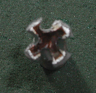
It was also necessary to cut a series of grooves into the head for two reasons. First, the grooves would help provide adhesion to the mould material and second, they would provide passages from the area above the head to the area below the head when submerging the threaded core into the liquid mould material.
11
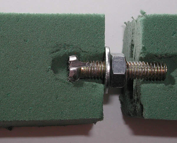
When the screw has been ground to an appropriate size and shape, lay it into half of the Oasis block mould to verify that the size & shape is appropriate and that it will form a good core for the new mounting post. If the screw appears too big, grind it down further until you're certain none of the metal would be exposed in the end. This is also the time to adjust the depth of the screw in the mould by winding the nut and washer to the appropriate location.
12
I found it easiest to use 5 Minute Epoxy as a moulding liquid. I knew that the epoxy would cure quickly, would be strong but wouldn't become brittle so it seemed like a good choice. I also had the good fortune of finding it at the local Dollarama for only $1.
13
Rejoin the two halves of the Oasis block mould, then fill the impression with expoxy.
14
Insert the formed screw into the epoxy-filled mould to the proper depth which was defined earlier by the position of the washer and nut. Make sure the mould is upright and allow the epoxy to cure.
15
Separate the Oasis block mould halves and remove the rough new mounting post. If you've ever handled a floral Oasis block before, you'll know that it's very brittle. It will easily separate and fragments will be stuck to the surface of the epoxy. Because it's so brittle, it's also very easy to brush off and clean away. What you're left with is a roughly formed epoxy mounting post with a threaded metal core.
16
Clean and shape the new mounting post to approximate the original (no phallus jokes please - we all know that's what the posts look like ). I shaped this one with a utility knife and a small file and was done in just a few minutes. To give the new mounting post a look of uniformity, I simply coloured the surface with a permanent black marker.
17
When the new mounting post is finished, cut the threaded shaft to an appropriate length. It's best if the shaft is long enough to reach the inner surface of the side cover. That will provide the maximum possible threaded length for anchorage in the mounting post base.
18
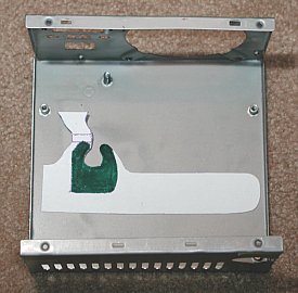
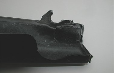
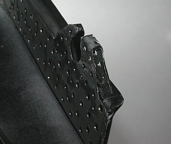
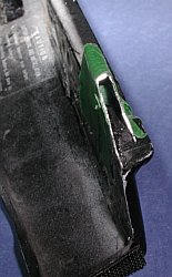
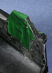
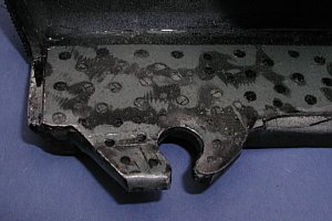
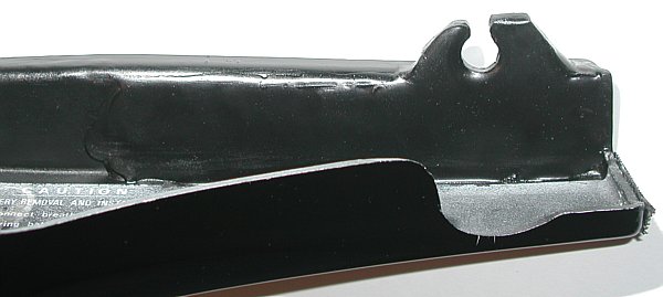
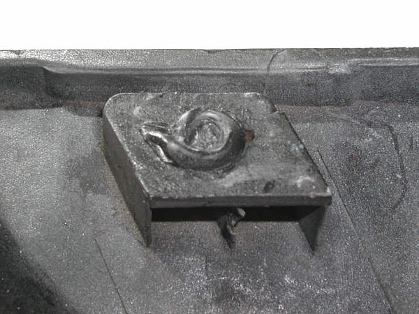
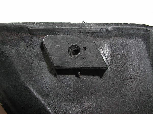
The side cover with the broken off post is certain to have an uneven break point. If, as in this case, it has previously been welded, there may also be a weld bead.
19
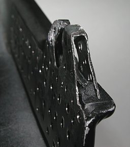
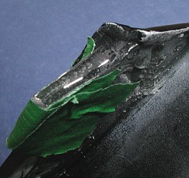
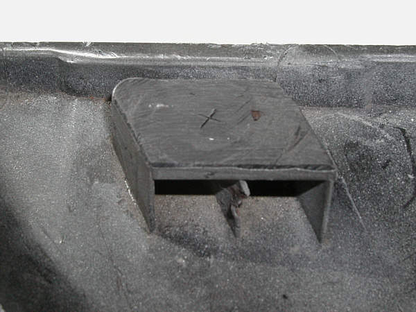
Prepare the top of the mounting post base by grinding it to a flat and reasonably smooth surface. I first cut away most of the weld bead with a utility knife then finished by resurfacing with a flat grinding stone. Once the top surface is flattened, locate and mark the center of the original post.
20
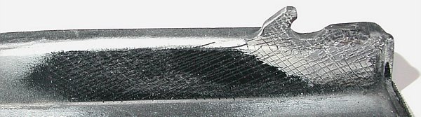
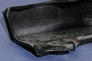
Drill a hole through the mounting post base, right to the inside surface of the side cover. The diameter of the hole should be slightly less than the thread diameter of the screw - in fact, the hole can be even a little smaller because the side cover material is a very soft plastic. There isn't much for the threads to screw into so a smaller hole will help keep the threaded part solidly in position.
21
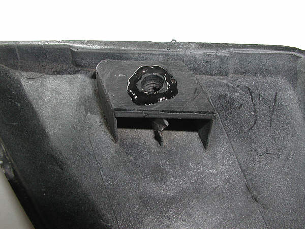
Apply a small bead of gel super glue around the hole where the washer will be.
22
Thread the new mounting post into the hole in the base until the washer is snug against the surface. Be careful not to get super glue on your fingers as you tighten the mounting post in place. If you didn't leave the threaded shaft too long, the washer should contact the base and adhere to the super glue before the threaded shaft contacts the inside surface of the side cover.
23
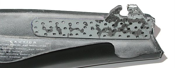
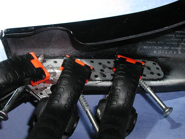
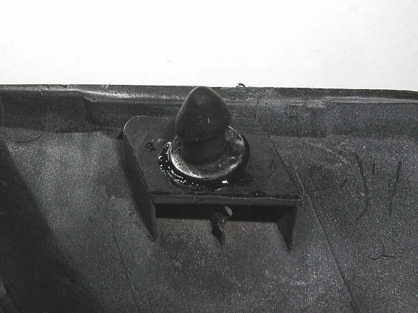
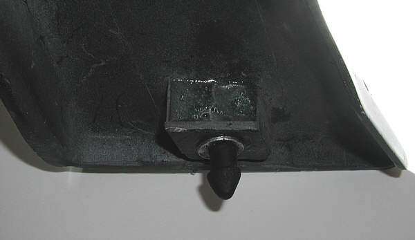
To finalize the repair, stand the side cover on its edge so that the open side of the mounting post base faces upward. Then fill the recesses below the mounting post base with epoxy. This will secure the threaded mounting post shaft in the base permanently (hopefully).

If everything went well, you should have a new bionic mounting post rigidly fastened to the side cover in the right location and depth. I guess it's worth mentioning that this has never been tried until now so there's no long-term feedback. It's not known how the epoxy will react to cold temperatures so anything is possible. When some time has passed and this repair has been proven to withstand time, temperature, force and vibration, I'll be sure to post the results.


February 2008 - Harald Pfeiffer (aka HAP)


Fixing a broken post-type mount on a side cover is one thing but fixing a broken "C"-type mount is something completely different. It's not the easiest thing you'll ever do but hopefully, with these instructions, it might not be the most difficult either.

Before tackling the repair on a buddies side cover (the same cover shown above for the post-type mount repair), I had to give it a lot of consideration but I eventually decided on a formed piece of sheet metal which seemed to work reasonably well. Hopefully the following pictures and comments will accurately convey how the job was done and with any luck, they'll inspire some creativity where others have to do similar repairs.

1
To repair the broken off and partly missing "C"-type side cover mount, it's again helpful to have a spare side cover as a template if there are no good mounts on your own cover. If you don't have a spare, then borrowing a side cover will also work. The borrowed cover won't be harmed in the process and would only be necessary very briefly.
2
The spare or borrowed cover must have a good "C"-type mount which you'll have to trace onto cardstock in order to get a template to overlay over a tracing of the broken mount later.
3
The next step is to get a tracing onto cardstock of the area surrounding the broken mount.
4
Overlay the good mount template onto the tracing of the bad mount in an appropriate alignment. That, if nothing else, should give you a good guide for forming the opening in the new mount when you get that far.
5
The next step requires a little creativity and an ability to extrapolate visually. The broken part of the mount will be formed from sheet metal on either side of an epoxy core so the tracing has to be expanded a bit to include the section that will eventually be folded over. You'll have to keep the symmetry in mind as you sketch an addition to the template for the fold over (outlined in yellow above).
6
When I started this repair I was short on sheet metal so I had to be creative there too. Being a "computer guy", I had plenty of old PC power supplies lying around. I just dismantled one that had burned out and traced the finished cardtock template onto the metal outer housing. You can use pretty much any metal you like but make sure it's a heavy enough gauge. The metal, when folded over, will form the structural base on which the broken part of the mount will be built. If the metal is too thin, it will be too flexible even over an epoxy core and it may not provide the strength needed to resist breaking when mounting and removing the side cover.
7
Although the shape of the template is likely to be fairly intricate like mine was, cutting the metal to shape isn't very difficult or time-consuming. I drilled out the hole in the centre of the mount then cut the rest of the shape using a 4" angle grinder with a metal cutting disc. After the cutting was finished, I deburred the edges with a file. The whole process was over in about 30 minutes - that's all it took.
8
Since there aren't any screws or other fasteners involved in this repair, it's necessary to make some modifications to the sheet metal. The metal will eventually be held in place by epoxy so drilling the metal full of small holes creates many anchorage points for improved adhesion. In the picture there are still undrilled areas but I later went on to drill those full of smaller holes as well. Without the holes, the smooth metal might separate from the epoxy layer in time, particularly after it's undergone many cycles of flexure, temperature and vibration.
9
The last step before putting the piece in place is to fold over the extrapolated extension which will form the outer shape and structural base of the missing piece of the mount. At this point the formed sheet metal should start to resemble something recognizable.
10
Before the repair, the broken "C"-type side cover mount looked like the picture above.

11
At this point the newly formed piece of metal can be tested in place and, if necessary, adjusted as well. If anyone wonders why I made the piece of metal so long for such a small broken area, it was to improve adhesion of the metal to the side cover. If the cover ever undergoes forces that would otherwise tend to dislodge the epoxy layer or the sheet metal piece, those forces will hopefully be dispursed over a greater surface area. No calculations were made since there isn't really a reliable way of quantifying the sort of forces a sidecover might undergo and since the scenarios leading to damage are endless and simply uncalculable. Let's just say it was a "guestimate" by someone who's seen this sort of repair in action before (me ).
12
After you're satisfied that the sheet metal piece fits properly into place and forms a good new mounting point, it's time to fasten it permanently in place. To do that you'll first have to clean and score the surface of the side cover over which the piece will be epoxied. A dirty or smooth surface will increase the chances of having the epoxy layer pull away from the side cover. Scoring is most important because it provides good anchorage points for the epoxy layer. I scored the surface with a simple utility knife in a cross-hatch pattern.
13
To secure the new piece, apply a layer of epoxy onto the scored side cover, then clamp the perforated piece of sheet metal into place at several points to make sure it contacts the surface uniformly. You'll know your piece is clamped well when epoxy comes through all the holes evenly. Of course, your clamps would be forever fastened to the side cover if they weren't protected somehow. I was short on ideas to keep them free of the epoxy so I decided to lay some screws between the clamps and the epoxied sheet metal. It wasn't optimal but it kept the clamps clean and I knew I had a reasonably good chance of dislodging the screws afterwards.
14
After the epoxy has cured and you've managed to remove whatever you used to elevate the clamps, there's still some more to do. The epoxy layer has so far only served to anchor the sheet metal piece to the side cover but, at this stage, the focal point of the repair (the broken piece of the mount) is still unfinished. It's hollow and flexible and has too little strength to serve its purpose effectively. To finalize the area around the break it's necessary to fill the hollow space (the broken away piece) with epoxy to, in effect, create a stronger laminate material in the critical area. I simply surrounded the area in masking tape, closing off all openings excluding the long end into which I poured the epoxy. On their own, the two layers of sheet metal surrounding an air space can easily be bent and damaged but when the air space is filled with epoxy, the area becomes a structural element that's considerably stronger and more resilient than the original soft plastic (ABS?) of which the side cover is made.
15
When the epoxy cures, remove the masking tape and the repair is almost done. For aesthetics only, I put another layer of epoxy across the finished product just to smooth out the uneven areas and the spots where I removed the stuck screws. The result was a fairly clean and structurally solid repair.
16
Just to finish things off, I sanded the epoxy smooth, cleaned up the edges and sprayed on a couple of coats of black flexible trim paint. The repair isn't invisible but it's respectably clean and more importantly, it's solid. I deliberately left one side of the mount larger for added strength and I resisted the urge to widen the opening in the mount in case the grommet on the bike had worn with age. The hole and the opening can always be enlarged, if necessary, with a grinding drill bit and grinding dis c.
As with the earlier post repair, if everything went well, you should have a new bionic side cover mount. Only time will tell how well this repair withstands temperature, force and vibration but I'm reasonably sure it will hold up because I've done this repair several times on other bikes.


February 2008 - Harald Pfeiffer (aka HAP)